Designing Organizations Around Value
A structural design discipline for complex product development systems.
Introduction – Designing for Sustained Flow
In complex product development, performance depends on flow. Lead times, feedback cycles, variability, and the synchronization of interdependent work determine how quickly and how reliably increments converge into integrated and testable outcomes. These dynamics directly influence delivery speed, learning, and risk exposure.
Organizing around value establishes the structural conditions under which such flow can be sustained. It is the second stage of the Value Stream Lifecycle – building on the understanding developed during identification and creating the foundation that systematic optimization depends on. However, aligning work with value streams alone does not yet determine how the organization should be structured.
As discussed in Team as the Smallest Unit of Value Delivery, the team forms the smallest organizational unit capable of containing integration sustainably. Within a well-designed team, cross-disciplinary trade-offs, design decisions, and validation activities can occur locally without excessive coordination overhead.
Most products, however, exceed the scope of a single team. Modern product development systems often involve dozens or even hundreds of teams contributing to shared architectures, platforms, and product capabilities. Architecture evolution, system validation, platform services, regulatory verification, and large-scale integration therefore require coordination across entire systems of teams rather than isolated collaboration between a few groups. At this scale, the organizational design challenge changes fundamentally.
The central question is no longer how a single team operates internally. The challenge becomes: how should many teams be composed into larger structures so that their work continues to converge reliably while coordination overhead remains manageable?
Designing organizations around value therefore means designing systems of teams – structures in which many teams can integrate their work predictably while maintaining sustainable flow. Whether a structural design actually delivers what it promises is ultimately determined by the four performance parameters of the development value stream: Time to Market, Productivity, Quality, and Employee Engagement. These parameters are deeply interconnected and mutually dependent – faster delivery depends on quality and reliable flow, sustained productivity requires engaged teams, and quality cannot be achieved without fast feedback and alignment. No matter how logically sound the organizational design appears on paper, it is these four parameters that reveal whether the structure enables or constrains value delivery in practice.
The Structural Design Problem
Organizational design in complex product development is fundamentally a question of where integration occurs and how it is coordinated.
Every product must continuously integrate contributions from multiple disciplines, components, and decisions. Software, mechanical design, electronics, safety constraints, and operational considerations must converge into a coherent system.
Integration is therefore not a final phase of development. It is a continuous structural activity that accompanies the entire value stream.
Organizational boundaries determine how this activity unfolds. If integration occurs within stable boundaries, work can converge smoothly. If integration requires repeated cross-boundary coordination, delays, queues, and synchronization overhead accumulate.
Designing organizations around value is therefore fundamentally about designing integration boundaries across the system that allow work to converge reliably while minimizing cross-team coordination overhead.
Integration Boundaries as Organizational Units
Integration boundaries define where design decisions, implementation work, and validation activities must converge frequently enough to be coordinated within a stable organizational unit. Within such a boundary, teams can collaborate continuously, integrate changes frequently, and resolve issues without excessive cross-team coordination.
Depending on system scope and cognitive load, this unit may consist of a single team, or a stable team-of-teams structure composed of multiple closely collaborating teams. Many large-scale frameworks introduce structures that approximate such units – Agile Release Trains in SAFe, Nexus units, Requirement Areas in LeSS, Tribes in the Spotify model, and Scrum-of-Scrums setups in Scrum@Scale – though their effectiveness depends on how well the chosen grouping reflects the underlying system structure rather than organisational convenience.
As a general design rule, integration boundaries should be placed where work must converge frequently, architectural dependencies are dense, and stable collaboration can absorb coordination without excessive overhead.
The Structure of an Integration Boundary
Every integration boundary – whether at team level, sub-stream level, or value stream level – follows the same structural pattern.
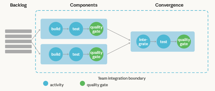
A backlog feeds parallel activities. Those activities – merging, building, testing, validating non-functional requirements, or any other work the context demands – process the incoming work within the boundary. A quality gate then determines readiness: it represents the acceptance criteria that must be fulfilled before the resulting Software Under Test can be pulled by the next integration level. The downstream level does not receive output passively – it pulls when criteria are met. This is a pull system, not a push.
This pattern is the structural atom of organizational design in complex product development. It defines what an integration boundary is in operational terms: not an organisational box on a chart, but a unit of convergence with a defined input, a defined set of activities, and a defined readiness signal.
What determines whether a single team or a team-of-teams structure is appropriate within this boundary is primarily cognitive load – the scope of the system must not exceed what the boundary’s members can sustainably understand and evolve. This is explored in detail in the Fracture Planes lens below.
The pattern is also recursive. Integration boundaries compose into systems of teams, where each level follows the same Backlog → Activities → Quality Gate → Pull logic at a larger scope. A sub-stream integration boundary takes team-level SUTs as its input, processes them through integration and validation activities, and produces a sub-stream-level SUT that the next level can pull. The value stream boundary does the same with sub-stream outputs. The structural logic is identical at every level – only the unit of work and the scope of validation change.
This recursive structure, and its implications for scaling, are explored in the Scaling section below.
As a general design rule, integration boundaries should be placed where work must converge frequently, architectural dependencies are dense, and stable collaboration can absorb coordination without excessive overhead. When these conditions hold, teams within the boundary can integrate continuously and resolve issues locally. When boundaries are misplaced – cutting across frequent coordination needs rather than containing them – the same coordination that could happen as a conversation within a team becomes a formal dependency between teams.
Dependencies inside a team are experienced as collaboration. The same dependencies across organisational boundaries become coordination overhead.
From Flow Observation to Structural Design
Understanding these dynamics allows us to move from symptom observation to structural design decisions.
Designing integration boundaries therefore requires more than observing flow dynamics alone.
Organizational structure is shaped by multiple forces: how work moves through the value stream, where natural segmentation points occur, how the architecture organizes technical dependencies, and how communication structures influence coordination.
The following cascade illustrates how organizations move from observing flow behavior to designing systems of teams that enable reliable product convergence.
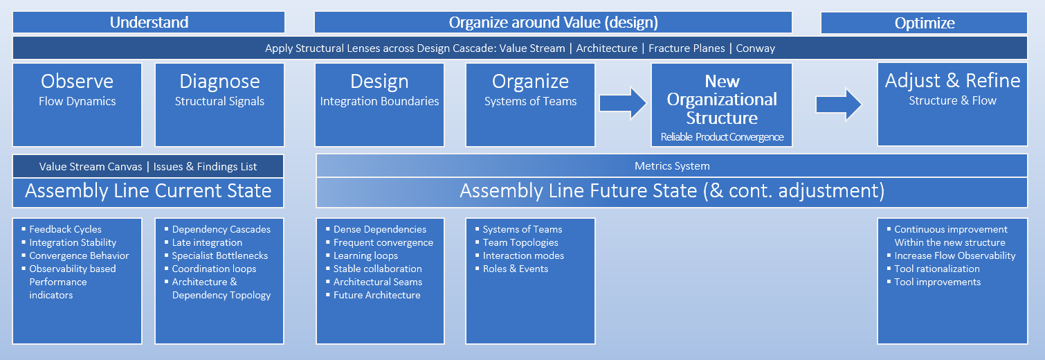
Organizational design follows a structural cascade that moves from understanding system behavior to establishing a stable organizational structure.
Observe – Flow Dynamics: Organizational design begins by observing how work actually behaves in the value stream. The Assembly Line (current state) model provides the primary instrument for making this behavior visible. By mapping the stages, transitions, integration points, and validation loops of the value stream, the Assembly Line exposes how work actually progresses through the system and where time accumulates.
- Feedback cycles reveal where learning occurs and how quickly the system responds to change.
- Integration stability shows whether work converges smoothly or repeatedly destabilizes during integration.
- Observability through performance indicators reveals where delays accumulate or queues emerge.
Diagnose – Structural Signals: These observations must then be interpreted to identify the structural causes behind the observed behavior. Dependency cascades, late integration, specialist bottlenecks, and coordination loops reveal where the current organization forces excessive cross-team coordination or unstable feedback cycles.
Design – Integration Boundaries: The Assembly Line (future state) model translates the structural insights from observation and diagnosis into a redesigned flow structure. By defining stages, integration boundaries, validation loops, and coordination points, the future-state Assembly Line describes how work should progress through the system so that integration occurs within stable collaboration units and product increments converge reliably.
Organize – Systems of Teams: Once integration boundaries are defined, teams and team-of-teams structures are composed to operate within these boundaries. The Assembly Line (future state) model now becomes the structural coordination model in which these teams are placed. By assigning teams, team-of-teams structures, external dependencies, and relevant external parties to the stages and integration points of the Assembly Line, the organization makes explicit who owns which part of the flow and where coordination must occur. Teams represent the smallest stable integration unit capable of sustaining reliable flow. Larger products require systems of teams, whose interaction structures ensure that work continues toconverge reliably into integrated and validated product increments.
Result – Reliable Product Convergence: When structural design successfully addresses the problems revealed by flow dynamics, the system can achieve reliable product convergence – the predictable integration and validation of product increments.
Adjust & Refine – Structure & Flow: Once the new organizational structure is established, the focus shifts to continuous optimization within that structure. This requires increasing observability of the system by sharpening the metrics system and strengthening operational feedback. These signals reveal remaining delays, coordination friction, and improvement opportunities. The Assembly Line model continues to serve as the reference for analyzing system behavior and guiding targeted improvements, as described in Using the Assembly Line Approach for Value Stream Optimization.
To reason about these structural design choices systematically, we introduce four complementary lenses that reveal different constraints on organizational design.
The Four Structural Lenses of Value Stream Design
Each lens reveals a different constraint on how integration boundaries can be drawn and highlights a distinct dimension of the system:
- Value Streams – the dynamic lens
Reveal how work behaves over time. - Fracture Planes1– the segmentation lens
Reveal where structural boundaries can be placed. - Architecture – the technical lens
Reveals dependency density and integration cost. - Conway’s Law – the social lens
Reveals how communication structures shape system structure.
Each lens exposes a different constraint on organizational design. Sustainable flow emerges only when these perspectives are aligned in the resulting organizational structure.
When these lenses are misaligned, flow degrades regardless of the structural model applied. Designing organizations around value therefore means integrating these perspectives into a coherent system.
1. Value Streams – The Dynamic Lens
The Value Stream reveals the organization in motion. Instead of focusing on formal structures or reporting lines, it exposes how work actually progresses from intent to outcome and how the system behaves over time.
From this perspective, the system is observed through its flow behavior. Work moves through stages of planning, implementation, integration, validation, and release, forming a dynamic pattern of progress, delay, and learning.
The dynamic lens reveals how the system behaves under real delivery conditions, including:
Dynamics describe how work behaves as it moves through this system. They include:
- where work accumulates and queues emerge
- where feedback cycles close quickly or become delayed
- where integration stabilizes or repeatedly destabilizes
- where variability propagates across the system
These patterns reveal how the current structure influences flow.
The Assembly Line model makes these dynamics visible. By mapping stages, transitions, validation points, and handoffs, it reveals where work waits, where feedback cycles slow down, and where integration depends on fragile synchronization. In doing so, the Assembly Line exposes not only how the system is organized, but how it actually behaves during delivery.
The purpose of the dynamic lens is therefore not merely to observe flow, but to diagnose where integration boundaries and coordination structures must change.
When current-state analysis surfaces recurring delays, unstable feedback loops, or structural bottlenecks, these patterns become structural signals. They are captured in the Issues & Findings list and indicate where the current structure constrains flow.
The purpose of the dynamic lens is therefore not merely to observe flow, but to diagnose where integration boundaries and coordination structures must change. In this way, the dynamic lens connects flow observation with structural design by translating flow behavior into structural signals.
Design Implication – The Dynamic Lens
Flow dynamics reveal where integration occurs too late, too often across boundaries, or under unstable coordination conditions. When observing the value stream through the Assembly Line model, these patterns become visible as structural signals that indicate where the current organizational structure constrains flow. Organizational redesign therefore focuses on repositioning integration boundaries so that frequent learning and coordination occur within stable teams or teams-of-teams.
Typical signals include:
(a) Feedback cycles that require repeated coordination across many independent teams rather than within a stable team or team-of-teams
Example:
A feature requires changes across three components, each owned by a separate development team. Component testing is handled by a dedicated test team, and system integration is managed by yet another team. From the outset, implementing the feature requires coordinating requirements, design decisions, and timing across five separate teams – each with their own backlog priorities and cadences. When a defect appears during system integration that only manifests in the integrated system, the investigation requires coordination across all five teams before the root cause can be identified. What could have been a conversation within a single cross-functional team becomes a multi-week coordination effort involving scheduling, escalation, and context reconstruction across organizational boundaries.
(b) Validation that occurs primarily at late integration milestones rather than continuously along the flow
Example:
Subsystem teams develop their components independently and verify functionality using local tests. Full system validation occurs only during scheduled integration milestones late in the release cycle. When incompatibilities appear, large batches of changes must be analyzed simultaneously, making it difficult to isolate root causes and forcing multiple teams to coordinate rework.
(c) Shared specialist bottlenecks that create queues
Example:
Several development teams depend on a small number of safety engineers to review design changes before implementation can proceed. Because the specialists are shared across many teams, review requests accumulate in queues. Because the specialist team optimizes for their own throughput and standards while the development team optimizes for shipping, their goals are not aligned by default — adding friction and negotiation to every interaction.2
(d) Coordination loops that repeatedly delay convergence
Example:
A change to a subsystem interface requires updates in several dependent components owned by different teams. Each team must adjust its implementation and revalidate its changes before integration can proceed. Because the teams work on different cadences and priorities, multiple rounds of coordination are required before the system converges again.
When such patterns appear, integration boundaries are often misplaced.
Redesign therefore focuses on reducing the distance between action and feedback, allowing work to converge within stable organizational units whenever possible.
Determining where such boundaries should be placed cannot be derived from flow observation alone. It requires identifying where the system can be segmented into coherent units that can absorb frequent coordination and integration. This requires a second perspective: fracture planes.
2. Fracture Planes – The Segmentation Lens
While the dynamic lens reveals where flow becomes unstable, it does not yet determine where organizational boundaries should be placed. To answer that question, we must examine the system from a different perspective: how work can be segmented into coherent units.
Fracture planes describe natural segmentation points within a system where cohesion is high within the boundary and dependencies across the boundary are comparatively lower. In other words, they represent places where the system naturally tends to split into stable collaboration units.
When organizational boundaries align with such planes, frequent coordination occurs within stable teams, while cross-boundary interaction becomes less frequent and easier to manage. When boundaries cut across fracture planes, the opposite effect occurs. Dependencies increase, integration becomes fragile, and coordination overhead accumulates.
Fracture planes therefore represent natural candidates for integration boundaries that later translate into team boundaries.
Sources of Fracture Planes
Fracture planes do not arise arbitrarily. They typically emerge from structural characteristics of the system itself.
Common sources include:
- Subsystem boundaries
Technical components with strong internal cohesion and well-defined interfaces. - Business capabilities
Product or service capabilities that evolve semi-independently and deliver recognizable value. - Platform services
Shared technical capabilities used by many teams, such as infrastructure services, developer platforms, or shared data services. - Regulatory domains
Areas governed by distinct compliance, certification, or safety requirements. - Product modules
Architectural units3 that can evolve somewhat independently within the larger system.
These sources describe where systems naturally segment due to technical structure, product capabilities, or domain constraints. In practice, the emergence of fracture planes is shaped by three structural factors:
|
Structural factor |
Role |
|---|---|
|
Cohesion |
conceptual integrity |
|
Interaction frequency |
operational integration need |
|
Cognitive load |
limit of stable collaboration |
Fracture planes determine where the system should split based on cohesion and interaction frequency, while cognitive load determines how large each resulting collaboration boundary can be.
Even when a fracture plane defines a coherent subsystem or capability with strong cohesion and interaction frequency, the scope may still exceed what a single team can effectively understand and evolve. In such cases, the segment must be subdivided into multiple teams while preserving the underlying structural boundary.
These teams then operate as a stable team-of-teams integration unit within the same integration boundary, allowing frequent coordination and learning to occur within the boundary while distributing cognitive load across multiple teams.
Structural Signal – Dependency Density
Dependency density reveals how frequently different parts of the system must interact during development and integration.
When components interact frequently – through shared data, coordinated changes, or repeated integration points – their work must converge regularly. Separating the responsible teams across organizational boundaries in such situations
often introduces coordination overhead, synchronization delays, and unstable feedback cycles.
High dependency density therefore signals that the affected components may belong within the same integration boundary, typically implemented as a single team or a stable team-of-teams structure.
Conversely, areas with low interaction frequency and stable interfaces can often be separated safely into independent teams.
Dependency density therefore acts as an empirical indicator for whether fracture planes are viable and where integration boundaries should remain intact.
Design Implication – The Segmentation Lens
When redesigning an organization around value, fracture planes guide where integration boundaries should be placed.
Typical structural moves include:
- grouping tightly coupled components within the same team or team-of-teams
- separating loosely coupled subsystems into independent teams
- aligning team boundaries with architectural modules or product capabilities
- removing boundaries that cut across frequent learning and integration loops
The goal of organizational design is to minimize dependencies wherever possible. When dependencies cannot be avoided, boundaries should be placed so that the remaining dependencies occur within stable collaboration units.
Dependencies inside a team are experienced as collaboration.
The same dependencies across organizational boundaries become coordination overhead.
Within a stable team or team-of-teams structure, coordination is immediate: questions can be clarified quickly, trade-offs can be negotiated directly, and integration occurs continuously as part of the work. Across organizational boundaries, the same interaction becomes slower and more costly because communication requires scheduling, priorities must be negotiated, and work may wait for availability or approval.
Organizational Patterns Along Fracture Planes
Team Topologies provides practical patterns for organizing along these boundaries.
- Stream-aligned teams take end-to-end responsibility for a coherent flow of change.
- Platform teams absorb recurring cross-cutting capabilities.
- Enabling teams help reduce cognitive load where specialized expertise is required.
- Complicated subsystem teams isolate domains with unusually high technical complexity.
These patterns should not be treated as templates. They represent recurring responses to the dependency topology of complex systems. Different systems will require different combinations of these patterns depending on architecture, dependency density, and cognitive load constraints. However, even well-segmented systems often exceed the scope of a single team.
This leads to the next structural challenge: scaling integration beyond a single team.
Scaling – Systems of Teams
Even when organizational boundaries align with natural fracture planes, the scope of the system may exceed what a single team can contain.
Scaling becomes necessary when either of two conditions emerges.
First, cognitive load may exceed what a single team can sustainably manage.
Some subsystems require architectural scope, domain expertise, or operational context beyond the capacity of one team.
Second, integration scope may exceed a single team.
System-level validation, shared platforms, regulatory verification, or large-scale architecture evolution often require coordinated work across multiple teams.
When this occurs, integration must take place at a higher structural level.
Scaling therefore means designing nested convergence structures – organizational layers where integration and validation occur at progressively larger scopes.
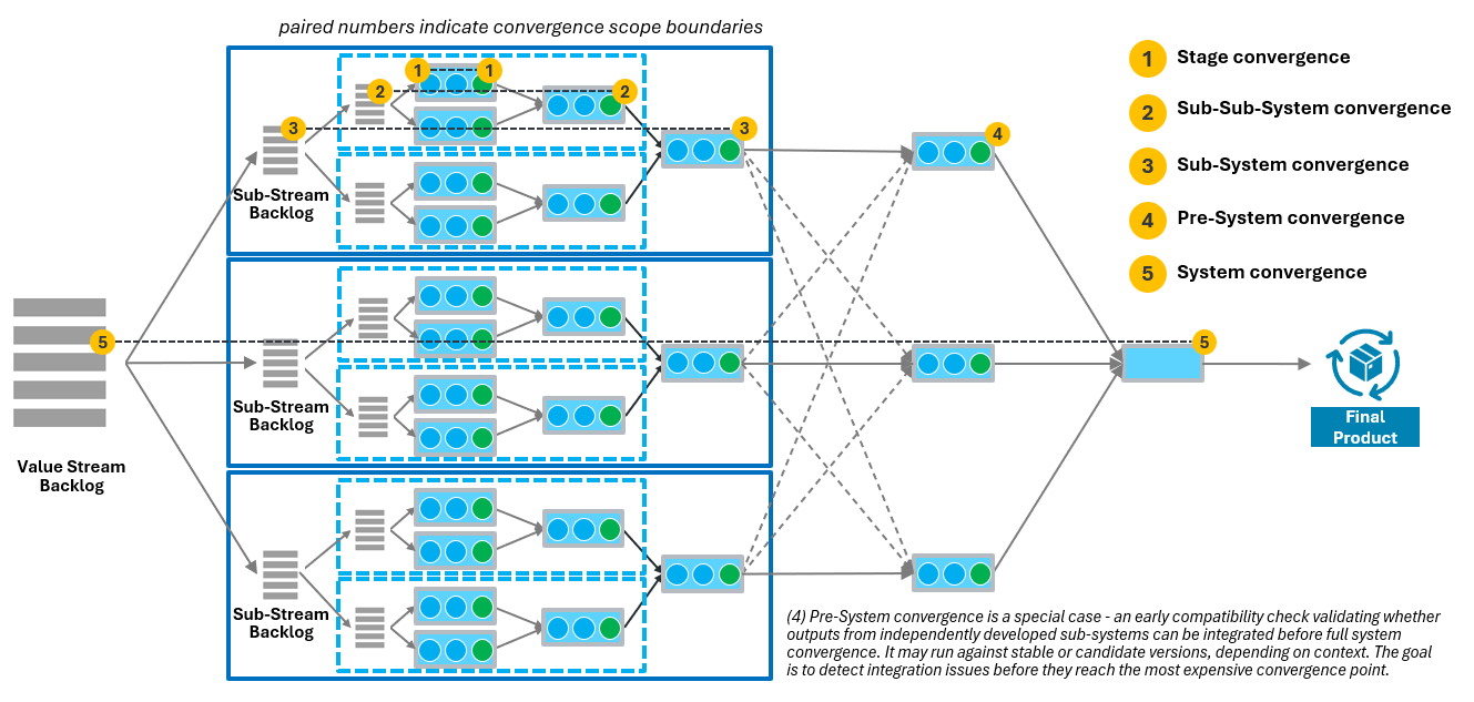
At each level, the goal remains the same: ensure that work converges predictably while keeping coordination overhead manageable.
Scaling structures must therefore define:
- shared validation scope
- synchronization rhythms
- integration responsibility
- coordination mechanisms4
Poorly designed scaling structures lead to expanding coordination forums, unstable integration phases, and persistent cross-team dependencies. Well-designed systems of teams maintain flow even as system complexity increases.
3. Architecture – The Technical Lens
While fracture planes reveal where systems can be segmented conceptually, the technical architecture determines how feasible and stable such segmentation is in practice.
Every architectural design creates a network of dependencies between components. These dependencies determine how frequently different parts of the system must interact, how costly integration becomes, and how independently teams can evolve their parts of the system.
Architecture therefore acts as a structural constraint on organizational design. Tightly coupled components require frequent coordination between the teams responsible for them, while modular components with stable interfaces allow teams to operate with greater autonomy.
In this sense, architecture defines the dependency topology of the system.
Coupling and Integration Frequency
Not all dependencies have the same impact on organizational structure. The critical factor is integration frequency.
Components that must integrate frequently during development require tight coordination between the teams responsible for them. Separating such components across distant organizational boundaries often leads to repeated synchronization effort, delayed feedback, and unstable integration phases.
Conversely, components that interact infrequently or through stable interfaces can be developed more independently.
Architectural coupling therefore acts as a strong indicator for where integration boundaries should – or should not – be placed.
Architectural Modularity
Well-structured architectures provide natural seams that support organizational segmentation. These architectural seams often correspond to what software architecture literature describes as fracture planes – natural splitting points where systems can evolve with limited cross-component coordination.
Modular architectures typically exhibit the following properties:
- clear and stable interfaces between components
- strong internal cohesion within modules
- limited dependency propagation across modules
- predictable integration points
When these conditions are present, teams can evolve modules with limited coordination overhead. When they are absent, integration becomes fragile and coordination cost increases significantly.
This is why architectural modularity often becomes a prerequisite for effective organizational autonomy.
Architectural Evolution and Organizational Design
Architecture and organization rarely evolve independently. When teams are reorganized without corresponding architectural changes, the resulting boundaries often conflict with the existing dependency structure. Teams then remain tightly coupled despite formal separation.
Conversely, architectural refactoring often enables new organizational structures by reducing dependency density between components.
In practice, architecture and organization co-evolve:
- architectural modularization enables team autonomy
- stable team ownership encourages modular design
- frequent cross-team coordination often signals architectural coupling
Recognizing this mutual influence is essential when redesigning organizations around value.
Design Implication – The Technical Lens
The architecture lens reveals where technical dependencies constrain organizational design and where architectural structure forces coordination between teams. When architectural boundaries and organizational boundaries are misaligned, integration effort increases and coordination becomes structurally unavoidable. Technical mechanisms such as interface versioning, backward compatibility, or contract testing can reduce coordination cost, but they cannot eliminate the underlying dependencies. Organizational design should therefore minimize the need for such compensating mechanisms by aligning team responsibilities with architectural seams.
Typical architectural signals include:
(a) Dependency cascades
Example:
A modification to a shared authentication service requires updates across several dependent services owned by different teams. Even when interface versioning is used, teams must coordinate migration, validation, and deployment timing before the change can be safely released.
Dependency cascades indicate that local changes propagate widely across the system. In well-modularized architectures, most changes should remain local to a component or subsystem. When changes repeatedly propagate across team boundaries, the architecture creates structural coupling that forces coordination between teams.
(b) Integration bottleneck components
Example:
A central configuration service is modified by multiple teams. Because changes affect many dependent systems, updates must be carefully coordinated and validated across the organization. Whenever multiple teams attempt to modify the component simultaneously, integration delays occur.
Such components often become coordination hubs where many development streams converge. They may accumulate review queues, release bottlenecks, or cross-team dependencies that slow the overall system.
(c) Integration that depends on synchronized releases
Example:
Two subsystems maintained by different teams must be released together because their interfaces evolve frequently. As a result, development progress slows because both teams must repeatedly synchronize release schedules and validation activities.
This pattern indicates tight architectural coupling between components. When release timing must be coordinated repeatedly, the architecture does not allow teams to evolve independently.
(d) System integration repeatedly exposes incompatible assumptions
Example:
Subsystems developed independently by different teams function correctly in their local environments but fail during system integration due to inconsistent assumptions about data formats, configuration, or timing behavior.
Such failures often reveal hidden dependencies in the architecture. These dependencies may not be visible at the interface level but emerge when multiple components interact within the integrated system.
(e) Local changes require system-wide understanding
Example:
To safely modify a component, developers must understand behavior across several services because interactions are difficult to isolate. Teams frequently consult other teams before implementing changes, slowing development and increasing coordination overhead.
This signal often indicates that the architecture lacks clear modular boundaries, forcing teams to reason about large portions of the system even for small changes.
When such patterns appear, organizational boundaries often conflict with the system’s dependency topology.
Architectural design therefore plays a critical role in organizational design. In well-designed systems, architectural seams often become natural candidates for team ownership. By designing for modularity, stable interfaces, and limited dependency propagation, architects can reduce the coordination required between teams.
Organizational redesign must then align team responsibilities with architectural seams so that most changes can be implemented, validated, and integrated within stable collaboration units rather than across many independent teams.
In well-structured systems, architectural boundaries often become natural candidates for team boundaries.
Architecture determines the cost of coordination.
Organization determines how that coordination is performed.
Architectural signals reveal where the system forces coordination between teams. Organizational design should therefore combine architectural evolution with organizational alignment: reducing unnecessary dependencies where possible and placing integration boundaries where unavoidable coordination can occur within stable team or team-of-teams structures.
Architectural Alignment and Integration Boundaries
Architectural structure and organizational structure must therefore be aligned so that team boundaries reflect the system’s dependency topology.
Integration boundaries should ideally coincide with architectural seams where:
- dependencies across the boundary are limited
- interfaces remain relatively stable
- integration occurs at predictable points.
When these conditions hold, teams can evolve their components with minimal coordination overhead while maintaining reliable system integration.
However, architecture alone does not determine the final organizational design. Even well-modularized systems may still experience coordination constraints arising from communication structures and organizational dynamics.
To understand these forces, we must examine the final perspective: Conway’s Law5.
4. Conway’s Law – The Social Lens
Even with well-defined boundaries and modular architecture, integration ultimately depends on how people communicate.
Conway’s Law observes that systems mirror the communication structures of the organizations that build them. If communication paths are misaligned with architectural boundaries, coordination becomes fragmented and integration problems emerge.
In practice, this means that organizational boundaries influence where coordination occurs during development. When teams must collaborate frequently to implement or modify a component, communication paths tend to shape the resulting architecture.
Organizational design must therefore consider:
- communication channels
- decision authority
- coordination structures
- governance mechanisms
The social structure of the organization must support the architectural and segmentation choices made earlier.
Design Implication – The Social Lens
Conway’s Law highlights that communication structures shape system architecture. Organizational boundaries therefore influence how components evolve, where coordination occurs, and how integration problems emerge.
When communication paths are misaligned with architectural dependencies or integration boundaries, teams must repeatedly coordinate across organizational boundaries. This increases coordination overhead and often leads to architectural drift.
Effective organizational design therefore requires aligning communication structures, integration boundaries, and architectural seams so that the teams who must collaborate most frequently are positioned within stable collaboration units.
In practice, this often requires applying the Inverse Conway Maneuver6.
The Inverse Conway Maneuver deliberately designs team boundaries so that the desired architecture can emerge. Rather than allowing the system structure to evolve accidentally from existing communication paths, the organization is intentionally structured so that teams own coherent parts of the system and collaborate along predictable interfaces.
When applied deliberately, Conway’s Law becomes a design tool rather than a constraint.
Frameworks as Coordination Patterns
Many organizations turn to scaling frameworks such as SAFe, Nexus, Scrum@Scale, or the Spotify model to coordinate multiple teams. These frameworks provide valuable experience-based patterns for synchronization, governance, and collaboration. They can accelerate organizational evolution when applied in the appropriate context.
However, frameworks primarily address coordination mechanisms. They do not replace the need for structural design. If team boundaries, architectural modularity, and dependency topology are poorly aligned, coordination structures alone cannot restore flow. In such cases, the underlying structural segmentation must be reconsidered.
Frameworks stabilize coordination; they do not substitute for structural design.
From Structural Design to Continuous Optimization
The structural considerations described in this article correspond to the organizational design phase (stage 2) of Value Stream Thinking.
During this phase, organizations analyze the current value stream, identify structural constraints, and explore alternative configurations for teams, boundaries, and coordination mechanisms. Once a structurally coherent system has been established, attention can shift toward continuous optimization.
Flow metrics, feedback cycle times, defect flows, and deployment frequency provide insights into how effectively the system operates. Improvements then focus on refining synchronization, improving architectural modularity, and reducing remaining sources of delay.
Structural design establishes the foundation. Continuous improvement builds upon it.
Closing Perspective
Designing organizations around value is not primarily about adopting a particular framework or management model. It is about understanding how work flows through complex systems and deliberately shaping the structures that allow that work to converge.
When flow dynamics, structural segmentation, architecture, and communication patterns align, organizations can scale product development while maintaining both speed and reliability.
When they do not, coordination overhead inevitably replaces flow. Organizing around value therefore requires not only new practices, but a deeper understanding of how organizational structure and system behavior interact.
Notes & References
- The term fracture planes is used in Team Topologies to describe natural splitting points for team and software boundaries. It is conceptually related to bounded contexts in Domain-Driven Design, which identify coherent domain boundaries with strong internal cohesion and explicit interfaces to other domains.
– Evans, Eric – Domain-Driven Design: Tackling Complexity in the Heart of Software. Addison-Wesley, 2003.
– Skelton, Matthew; Pais, Manuel — Team Topologies: Organizing Business and Technology Teams for Fast Flow. IT Revolution Press, 2019. ↩︎ - When all participants share the same end-to-end goal – delivering working, validated software to the next stage – the conflict between local optimization and flow dissolves. This is one of the strongest arguments for cross-functional team design: shared ownership of the outcome removes the incentive to optimize locally at the expense of the whole. ↩︎
- Architectural units typically correspond to technical subsystems or modules that encapsulate a coherent set of responsibilities and expose well-defined interfaces to the rest of the system. Examples include an embedded control subsystem in a vehicle (e.g., powertrain control), a payment processing service in a digital platform, a user identity and authentication module, a data ingestion pipeline in an analytics system, or a recommendation engine within an online service.
Such units often represent natural candidates for team ownership because they combine strong internal cohesion with relatively stable external interfaces, allowing teams to evolve the unit while minimizing cross-team coordination.
When organizational boundaries align with such architectural seams:
• dependencies become more predictable
• integration becomes structured around explicit interfaces
• teams can evolve their components independently without continuous cross-team coordination. ↩︎ - Coordination mechanisms are a central element of every scaling framework. At the team level, Scrum defines a set of events that create regular opportunities for planning, alignment, inspection, and adaptation: Sprint Planning, Daily Scrum, Sprint Review, Sprint Retrospective, and Backlog Refinement. At the teams-of-teams level, SAFe introduces a complementary set of events operating at the Agile Release Train (ART) level: PI Planning, ART Sync, PO Sync, Scrum of Scrums, System Demo, and Inspect & Adapt. At the solution train level — where multiple ARTs coordinate – SAFe adds Pre- and Post-PI Planning and the Solution Demo. These events do not replace structural design; they operationalize it. Well-placed integration boundaries make these coordination events effective. Poorly placed boundaries make them necessary but insufficient – adding coordination overhead without resolving the underlying structural mismatch. ↩︎
- Conway’s Law originates from a paper titled „How Do Committees Invent?“ written by Melvin Conway and submitted to the Harvard Business Review in 1967. HBR rejected it on the grounds that Conway had not proved his thesis. The paper was subsequently published in April 1968 by Datamation, the leading IT journal of the time. Conway’s central observation was: „Any organization that designs a system (defined broadly) will produce a design whose structure is a copy of the organization’s communication structure.“ The law was not intended as a provocation but as a practical sociological observation — a consequence of the fact that two components cannot interface correctly unless the people responsible for them communicate effectively.
The term „Conway’s Law“ was coined by Fred Brooks in his influential book The Mythical Man-Month, first published in 1975. Brooks both named the concept and recognized its management implications, noting that because the first design of a system is almost never the best, organizational flexibility is essential to effective design. His endorsement gave Conway’s observation the visibility and the name that allowed it to travel far beyond its original context.
References:
– Conway, M. (1968). „How Do Committees Invent?“ Datamation, April 1968. Available at melconway.com
– Conway’s account and the law’s statement available at melconway.com/Home/Conways_Law.html
– Brooks, F. (1975). The Mythical Man-Month: Essays on Software Engineering. Addison-Wesley.
↩︎ - The term „Inverse Conway Maneuver“ was coined by Jonny LeRoy and Matt Simons of ThoughtWorks in an article titled „Dealing with Creaky Legacy Platforms,“ published in the December 2010 issue of the Cutter IT Journal. In that article, LeRoy and Simons observed that Conway’s Law — which states that the architecture of a system tends to mirror the communication structures of the organization that built it — can be summarized as „dysfunctional organizations tend to create dysfunctional applications.“ They proposed that before replacing a legacy system, it is worth investigating whether restructuring the organization or team could prevent the new system from inheriting the same structural dysfunctions as the original. What they termed an „inverse Conway maneuver“ — deliberately breaking down silos that constrain collaboration — could shape the resulting architecture before a line of new code was written. The concept was later documented by Martin Fowler on martinfowler.com.
Ruth Malan provided an influential modern formulation of Conway’s Law that underpins the maneuver: „If the architecture of the system and the architecture of the organization are at odds, the architecture of the organization wins.“ A related implication she drew out is equally important for organizational designers: „If we have managers deciding which services will be built, by which teams, we implicitly have managers deciding on the system architecture.“ Together these observations make explicit why deliberate organizational design — rather than leaving structure to historical accident — is a prerequisite for achieving the architecture a product development system actually needs.
Matthew Skelton and Manuel Pais brought the Inverse Conway Maneuver into mainstream practice with their book Team Topologies (2019). Where LeRoy and Simons identified the principle and Malan articulated the theoretical foundation, Skelton and Pais provided the practical framework — four team types (stream-aligned, platform, enabling, and complicated subsystem teams) and three interaction modes (collaboration, X-as-a-service, and facilitating) — that give organizations the vocabulary and patterns to apply the maneuver deliberately. Team Topologies positioned the Inverse Conway Maneuver not as a one-time restructuring exercise but as an ongoing organizational design discipline aligned with the evolution of the system architecture.
References:
– LeRoy, J. and Simons, M. (2010). „Dealing with Creaky Legacy Platforms.“ Cutter IT Journal, December 2010. Reproduced at jonnyleroy.com/2011/02/03/dealing-with-creaky-legacy-platforms/
– Fowler, M. „Conway’s Law.“ martinfowler.com/bliki/ConwaysLaw.html
– Malan, R. (2008). „A Trace in the Sand.“ ruthmalan.com/traceinthesand/conwayslaw.htm
– Skelton, M. and Pais, M. (2019). Team Topologies. IT Revolution Press. ↩︎
Author: Peter Vollmer – Last Updated on April 9, 2026 by Peter Vollmer